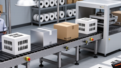
Choosing the 2026 best DMC data matrix code scanner requires more than comparing megapixels or advertised scanning speeds. Buyers should examine decoding reliability, lighting control, lens selection, software integration, and service support. In a real production cell, a scanner may face oily metal, curved plastic, low-contrast marks, vibration, and changing conveyor speeds. Small details matter.
Industry evidence supports this demand. MarketsandMarkets’ Machine Vision Market research identifies manufacturing inspection and traceability as major growth applications through this decade. The report also highlights increasing automation and quality-control requirements across industrial sectors. GS1’s Sunrise 2027 initiative is encouraging broader adoption of two-dimensional barcodes in retail, while Data Matrix remains important in manufacturing, healthcare packaging, electronics, and aerospace identification. These developments make reliable code reading a practical investment, not merely a technical upgrade.
Still, no scanner wins every line. A high-resolution camera can fail when glare overwhelms the symbol. A fast reader may struggle with shallow engraving or inconsistent print quality. This guide compares leading scanner types through measurable criteria, including read rate, depth of field, working distance, decoding time, IP protection, and integration options. It also considers evidence from manufacturer specifications, independent testing, and hands-on installation experience. Buyers should treat published performance figures carefully. Test conditions vary, and laboratory results may not represent a dusty factory floor. That limitation deserves attention. The strongest choice is usually the scanner that delivers stable reads with minimal maintenance, not the model with the most impressive brochure.
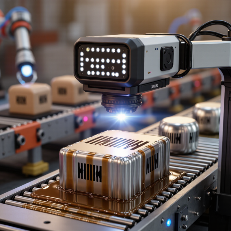
What Is a DMC Data Matrix Code Scanner?
A DMC Data Matrix code scanner reads two-dimensional symbols made from dark and light square cells. DMC usually refers to Data Matrix code, often used for traceability on parts, packaging, and small components. Unlike a traditional barcode, it stores information in a compact square area. It remains readable even when the printed surface is limited.
Most modern scanners use a camera, image processing, and decoding software. The scanner captures the symbol, identifies its border pattern, and converts the cell arrangement into usable data. Some codes are printed on labels, while others are directly marked on metal, plastic, or painted surfaces. Surface texture matters. Oil, glare, scratches, and weak contrast can reduce reading reliability.
A buyer should test the scanner with real samples, not perfect demonstration codes. Check reading distance, field of view, lighting control, connection options, and decoding speed. A fixed scanner may suit a conveyor, while a handheld model offers more flexibility. The scanner should also handle different symbol sizes and damaged codes through error correction. It is not magic.
In my experience, lighting is often overlooked. A strong reflection can hide several cells, even when the code looks clear to human eyes. Installation angles may need adjustment. Some specifications also sound impressive but fail in dusty production areas. Reviewing failure rates, maintenance needs, and operator feedback gives a more reliable purchasing picture than speed claims alone.
A DMC Data Matrix code scanner is an imaging scanner designed to read two-dimensional Data Matrix symbols, including ECC 200 codes. The chart compares the maximum payload capacity of the largest standardized ECC 200 symbol, a 144 × 144 module code, across common encoding modes. When choosing a scanner, buyers should confirm support for the required data type, fast decoding, low-contrast or damaged symbols, and the intended working distance.
A DMC scanner does not simply take a picture. It captures reflected light from tiny dark and bright cells. Integrated lighting helps reveal codes etched on metal, printed on labels, or marked on plastic. The scanner locates the square finder pattern, checks the quiet zone, and converts each cell into binary data. Error correction then reconstructs limited damage, often caused by scratches, glare, or uneven surfaces. The decoded message may contain a serial number, production date, or traceability record.
In a factory line, processing speed is only one part of performance. The scanner must handle motion, vibration, changing distances, and mixed surface finishes. It should also verify the result before sending data to a controller, database, or manufacturing system. A reliable setup uses controlled lighting, fixed mounting, and tested exposure settings. Field testing often reveals small weaknesses. A code that reads well on a workbench may fail beside oil, dust, or bright metal. No setup is perfect.
2026 Best DMC Data Matrix Code Scanner for Buyers?
Key Features to Compare in a 2026 DMC Scanner
Choosing a DMC scanner requires more than checking its advertised speed. A reliable model should decode ECC200 symbols on metal, plastic, labels, and uneven surfaces. High-resolution imaging helps read tiny cells, damaged marks, and low-contrast codes. Lighting control matters just as much. Red, blue, or diffuse illumination can reveal marks that ordinary white light misses. Speed matters. Compare actual decode times under factory lighting, not only laboratory results. In production trials, a scanner may perform well on flat samples but struggle with oily or curved parts. Test the awkward cases.
Autofocus and a wide working range can simplify inspections across different part sizes. Check whether the scanner supports continuous triggering, external sensors, and common industrial interfaces. Clear software should provide image capture, grading, failure statistics, and traceable records. A validation function is valuable when code quality affects inventory or assembly accuracy. Also inspect the enclosure rating, mounting options, cable strength, and operating temperature. These details sound minor until vibration loosens a bracket. Human factors deserve attention too. Operators need readable feedback and simple parameter changes. No scanner is perfect. A careful buyer should test ten or more real parts, including scratched, tilted, dirty, and poorly marked samples, before approving the purchase.
| Key Buying Criterion | Entry-Level Handheld Scanner | Industrial Handheld Scanner | Fixed-Mount Production Scanner | High-Speed Inline Vision Scanner |
|---|---|---|---|---|
| Best-Fit Application | General traceability, service desks, light manufacturing and occasional DMC reading. | Automotive, electronics, medical-device and warehouse environments with frequent scanning. | Automated stations, robotic cells, conveyors and controlled-position reading. | High-throughput inspection, serialization, grading and multi-code production lines. |
| Supported DMC Standard | ECC 200 Data Matrix; commonly supports square and rectangular symbols. | ECC 200 Data Matrix, including GS1 DataMatrix when configured for application identifiers. | ECC 200 Data Matrix with programmable decoding and image-based analysis. | ECC 200 Data Matrix with multi-code localization, quality analysis and configurable rules. |
| Typical Symbol Size | About 0.25–1.5 mm X-dimension, depending on print quality and contrast. | About 0.15–1.0 mm X-dimension under suitable lighting and working distance. | About 0.10–1.0 mm X-dimension, depending on lens, sensor and optics. | About 0.05–1.0 mm X-dimension with application-specific optics and lighting. |
| Maximum Data Capacity | Supports standard ECC 200 symbols up to approximately 2,335 alphanumeric characters in theory; practical capacity depends on print quality. | Supports the full ECC 200 range, including large symbols where the application and optical resolution permit. | Supports large ECC 200 symbols; actual limits depend on image resolution and field of view. | Supports large and multiple ECC 200 symbols, subject to processing speed, image resolution and code density. |
| Reading Distance | Typically close range, approximately 5–250 mm. | Typically approximately 50–500 mm, with interchangeable or extended-range optics on some configurations. | Typically approximately 50–800 mm, determined by lens, sensor and mounting geometry. | Typically approximately 100–1,500 mm, depending on optical setup and required field of view. |
| Damaged-Code Capability | Basic error correction for partially damaged ECC 200 symbols. | Enhanced image processing for low contrast, minor damage, uneven surfaces and direct-part marks. | Advanced decoding for damaged, low-contrast and partially obscured marks when lighting is optimized. | Advanced decoding plus inspection tools for grading, position, contrast and pattern defects. |
| Direct Part Marking Performance | Suitable for high-contrast laser marks and clean printed labels; limited on reflective metal. | Suitable for laser-etched, dot-peened and electro-chemical marks with correct illumination. | Strong option for fixed-position DPM applications using dedicated diffuse, dome or dark-field lighting. | Best suited to difficult DPM, reflective surfaces, variable mark quality and multiple viewing angles. |
| Image Sensor / Optics | Area-imaging sensor with general-purpose optics. | Higher-resolution area imager with industrial optics and configurable focus options. | Industrial area sensor with selectable focal length, field of view and exposure settings. | High-resolution area sensor with advanced optics, exposure control and optional liquid-lens focusing. |
| Illumination Requirements | Integrated LED illumination is normally sufficient for clean labels. | Integrated or interchangeable illumination is recommended for glare, curves and DPM. | External or built-in controlled lighting should be matched to the part surface and mark type. | Multi-angle, polarized, diffuse, dome or dark-field lighting may be required for reliable inspection. |
| Typical Decode Speed | Approximately 2–10 scans per second, depending on symbol size and condition. | Approximately 5–30 scans per second, depending on configuration and interface. | Approximately 20–100 frames or decode attempts per second, depending on image settings. | Approximately 30–200+ frames or decode attempts per second, depending on resolution and processing rules. |
| Multi-Code Reading | Usually limited to one code at a time or a small number of codes. | Suitable for several codes in one image, subject to firmware and field-of-view limits. | Designed for multiple codes in a controlled area with programmable output sequencing. | Designed for high-density multi-code reading, code matching and position-based validation. |
| Motion Tolerance | Low to moderate; best for presentation or short-distance manual scanning. | Moderate to high with suitable exposure, trigger timing and lighting. | High when the part position, trigger and conveyor speed are controlled. | Very high potential, provided shutter speed, illumination and line speed are correctly matched. |
| Ingress Protection | Commonly IP42–IP54, depending on enclosure design. | Commonly IP65–IP67 for dust and water protection in industrial use. | Commonly IP65–IP67; higher protection may require an enclosure or protective window. | Commonly IP65–IP67; complete system protection depends on camera, lighting and housing. |
| Drop / Vibration Suitability | Designed for normal office or light industrial handling. | Designed for repeated industrial handling and vibration within the stated product limits. | Designed for fixed installation; machine vibration isolation may still be necessary. | Designed for fixed installation; system mounting and vibration control are critical to image quality. |
| Connectivity | USB; wireless options may be available depending on configuration. | USB, Ethernet or industrial serial interfaces; wireless options may be available. | Ethernet, industrial Ethernet, RS-232, digital I/O or fieldbus through a controller. | Industrial Ethernet, fieldbus, digital I/O and controller or PLC integration. |
| Triggering Options | Manual trigger, presentation mode or software command. | Manual trigger, proximity sensing, serial command or external digital trigger. | Photoelectric sensor, encoder, PLC signal, software command or continuous mode. | Encoder-based, PLC-controlled, position-based or high-speed continuous triggering. |
| Verification and Quality Grading | Usually decode-only; verify quality externally if required. | May support basic quality indicators; confirm compliance requirements before purchase. | Often supports ISO/IEC 15415-based 2D quality grading with suitable software and setup. | Best suited to ISO/IEC 15415-based verification, trend monitoring and automated reject decisions. |
| Traceability Features | Decoded text output with basic application integration. | Data formatting, parsing, prefix/suffix rules and programmable output. | Code comparison, duplicate detection, job recipes and pass/fail output. | Advanced validation, serialization checks, database communication, OCR/OCV and audit records. |
| Operator Setup | Simple Basic configuration and quick deployment. | Moderate Requires application-specific setup for lighting and focus. | Advanced Requires mechanical, optical and control-system integration. | Advanced Requires imaging, inspection, networking and line-integration expertise. |
| Recommended Buyer Priority | Low purchase cost, ease of use, ergonomic handling and reliable reading of clean codes. | Durability, DPM capability, IP protection, flexible connectivity and stable performance. | Optical resolution, trigger control, repeatability, mounting flexibility and PLC integration. | Throughput, image quality, multi-code performance, verification, analytics and automation support. |
| Important Validation Test | Test the smallest code, lowest contrast and most common label angle in actual use. | Test representative DPM samples, glare, curved parts, damage and expected working distances. | Test at the real line speed with final lighting, mounting, vibration and trigger timing. | Test the complete production range, including worst-case marks, code density, reject logic and network load. |
The best DMC scanner depends on the buyer’s workflow, not only its resolution. ISO/IEC 16022 defines Data Matrix ECC 200, but real parts are rarely perfect. Metal surfaces may reflect light. Laser marks can fade. Tiny cells become difficult after cleaning or wear.
For automated lines, choose a fixed-mount scanner with adjustable lighting, high-speed decoding, and an industrial housing. MarketsandMarkets reported in 2024 that machine vision is expanding across manufacturing, driven by quality inspection and traceability. This supports fixed systems where every part passes the same camera position. However, installation errors still matter. Poor lighting can defeat an expensive scanner.
Handheld DMC scanners fit maintenance teams, warehouses, and mixed part sizes. Look for an aiming guide, broad depth of field, and reliable decoding on curved surfaces. Mobile or embedded scanners suit compact tools and point-of-use stations. A 2024 report from Grand View Research identified manufacturing as a major application area for 2D barcode readers, reflecting stronger demand for part-level tracking. Yet report statistics cannot predict your factory’s glare, dust, or operator habits. Test samples from normal production, including damaged marks. One sample is not enough. Capture failed scans, not just successful ones.