How to Choose the Right PNP Bipolar Transistor?
Choosing the right Pnp Bipolar Transistor begins with the circuit’s real demands, not a familiar part number. Voltage, collector current, gain, switching speed, and heat must work together. A transistor that survives a bench test may still fail inside a warm enclosure. That lesson appears often in repair and prototype work.
William Shockley, a pioneer of transistor engineering, is often credited with saying, “The transistor is the most important invention of the twentieth century.” His statement reflects the device’s lasting importance, but practical selection requires more than historical admiration. Engineers should compare the datasheet’s collector-emitter voltage, continuous collector current, DC current gain, saturation voltage, and transition frequency. These figures describe performance under specific conditions. They do not promise identical results in every circuit.
Look closely at the operating point. A Pnp Bipolar Transistor may need a negative base-emitter bias in a high-side switching stage. Check the resistor network, load current, and available base drive. Then inspect thermal resistance and the safe operating area. Small packages can become surprisingly hot near their current limits. Gain also varies widely between samples. That detail is easy to overlook.
A careful choice leaves margin. Usually.
This guide explains how to match electrical ratings, switching behavior, package design, and thermal performance with confidence. It also examines common selection mistakes, including trusting typical gain values or ignoring pulse conditions. Some recommendations remain conditional. Real circuits are imperfect, and measured behavior should challenge assumptions. A reliable Pnp Bipolar Transistor is selected through evidence, calculation, and practical testing.
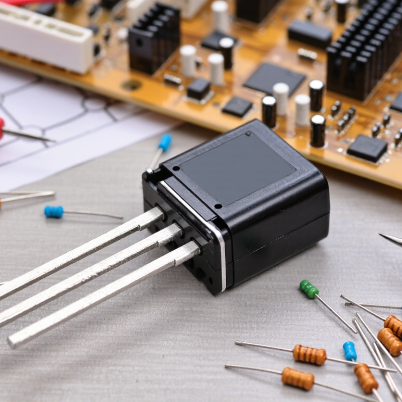
PNP Bipolar Transistor Fundamentals and Operating Principles
How to Choose the Right PNP Bipolar Transistor?
A PNP bipolar transistor conducts when its emitter is more positive than its base. In a silicon device, the base usually sits about 0.6–0.7 volts below the emitter. Conventional current enters the emitter and leaves through the collector. Base current flows outward through the base terminal. This direction often confuses new designers.
For high-side switching, connect the emitter to the positive rail. Pull the base lower to turn the device on. Select the transistor by checking collector current, emitter-collector voltage, power dissipation, and safe operating area. Do not design around typical hFE values. Production spread and temperature can change gain significantly. Use forced beta for switching calculations, then verify the base resistor with the controller’s actual voltage limits. Keep it practical.
Industry demand remains strong. WSTS forecast global semiconductor sales at 611.2 billion dollars in 2024, followed by 687.4 billion dollars in 2025. The Semiconductor Industry Association reported 526.8 billion dollars in 2023 sales. These figures include many device types, not only bipolar transistors, but they show why dependable component selection matters. JEDEC terminology also emphasizes rated temperature, leakage, and electrical test conditions. I still recheck these values under heat. A transistor that works on a cool bench may fail near its thermal limit. Look for VEC(sat), leakage current, package thermal resistance, and tested current conditions before choosing a part.
Identify Voltage, Current, and Power Requirements
Choosing the right PNP bipolar transistor starts with three questions: How much voltage, current, and power will it handle?
Measure the circuit, not only the nominal values. For voltage, check the maximum collector-emitter voltage, VCEO, and compare it with the highest supply voltage. Add practical margin for switching spikes and wiring errors. A 12-volt rail may briefly rise much higher. That detail is easy to miss.
Current needs equal attention. Estimate the largest collector current, IC, during startup, load changes, and permitted fault conditions. Do not use the absolute maximum rating as the normal operating point. If the load draws 600 milliamps, a 700-milliamp device leaves little breathing room. Base current also matters because a PNP transistor needs sufficient drive for efficient saturation. Check the forced beta value in the datasheet, rather than trusting the headline gain. Datasheets can be misunderstood.
Power is where many selections fail. Calculate transistor dissipation with P = VCE × IC under the worst realistic condition. During linear operation, heat may build quickly, even when current seems modest. Check junction temperature, thermal resistance, package limits, and airflow. A small package on a crowded board may need derating. I would test a prototype with a thermometer and oscilloscope, then compare measured temperature with the calculation. The first estimate is rarely perfect. Review switching speed, leakage, and safe operating area before approving the design.
Select and Validate the Transistor for Your Circuit Application
How to Choose the Right PNP Bipolar Transistor?
Select and Validate the Transistor for Your Circuit Application
A PNP bipolar transistor should be selected from circuit evidence, not only catalog numbers. Start with the load current, supply voltage, switching frequency, and available base-drive voltage. Keep collector-emitter voltage comfortably above the circuit maximum. A 20% margin is a practical starting point, but inductive loads may require more protection.
Check the datasheet under your real operating conditions. A transistor rated for 1 A may need substantial heat removal at elevated temperature. Calculate power using P = VCE × IC, then compare the result with the derated thermal resistance. Base current also matters. Forced beta provides a safer switching estimate than the headline gain value. That number can disappoint.
The Semiconductor Industry Association reported global semiconductor sales of 627.6 billion US dollars in 2024, showing the scale and pressure of modern component supply chains. However, market growth does not guarantee equivalent parts. Use the manufacturer’s qualification data, package drawings, and production status records. For automotive designs, AEC-Q101 test coverage can support validation, but it does not replace application testing. Build a prototype with the intended PCB layout. Measure voltage spikes, temperature rise, turn-off time, and leakage after thermal cycling. I would also test the weakest expected supply condition. Engineers sometimes overlook it. Recheck the design when the transistor operates near its limits.
How to Choose the Right PNP Bipolar Transistor? - Select and Validate the Transistor for Your Circuit Application
Representative engineering selection data for common PNP bipolar transistor applications
| Application Profile | Typical Circuit Function | Recommended VCEO | Recommended IC | Minimum hFE at Design Current | Target VCE(sat) | Typical fT | Suggested Package Class | Validation Focus |
| Low-Voltage Signal Switching | Sensor interfaces, level shifting, small indicator loads | 20–40 V | 10–100 mA | ≥100 | ≤0.25 V at IC = 50 mA | 100–300 MHz | Small-signal SMD or TO-92 | Confirm leakage, logic thresholds, noise, and pin configuration |
| General-Purpose Load Driver | Relays, solenoids, lamps, buzzers, and small motors | 40–80 V | 0.2–1 A | ≥80 | ≤0.35 V at IC = 0.5 A | 50–150 MHz | Power SMD or compact TO-126 | Check forced beta, transient suppression, and junction temperature |
| Medium-Power Switching | Power distribution, battery protection, and actuator control | 60–120 V | 1–5 A | ≥60 | ≤0.6 V at IC = 2 A | 20–100 MHz | TO-220, DPAK, or equivalent | Verify SOA, heat sinking, current gain at temperature, and switching loss |
| High-Voltage Switching | Automotive loads, industrial control, and flyback pre-drivers | 120–250 V | 0.1–2 A | ≥40 | ≤1.0 V at IC = 1 A | 10–60 MHz | High-voltage TO-126 or TO-220 | Allow voltage margin, test avalanche stress, and check turn-off behavior |
| Analog Amplifier | Audio stages, sensor gain blocks, and linear control circuits | 30–100 V | 1–500 mA | ≥150 | Not normally the primary criterion | 80–250 MHz | Low-noise SMD or TO-92 | Measure noise, matching, linearity, gain variation, and thermal drift |
| High-Speed Switching | Pulse circuits, fast level translators, and timing interfaces | 20–60 V | 10–300 mA | ≥100 | ≤0.3 V at the specified pulse current | 300–800 MHz | Small-signal SMD | Validate storage time, junction capacitance, rise/fall time, and layout parasitics |
Selection rule: Choose a PNP transistor with adequate voltage and current margin, then validate its worst-case power dissipation using PD ≈ VCE × IC. Confirm the safe operating area, thermal resistance, gain at the actual load current, base-drive capability, and maximum junction temperature under real operating conditions.