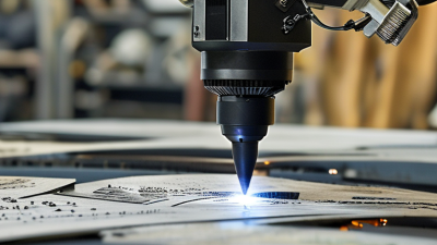
Choosing a sic marking laser in 2026 requires more than comparing wattage and price. Silicon carbide is hard, thermally stable, and often used in demanding electronic and industrial components. Its surface can react differently to fiber, UV, or ultrashort-pulse systems. The correct choice depends on material grade, coating, mark depth, line speed, and heat tolerance.
A practical evaluation should begin with production samples. Ask suppliers to mark your actual wafers, housings, or ceramic parts. Inspect contrast under factory lighting. Check edge quality with magnification. Measure cycle time, thermal impact, and readability after cleaning or coating. A reliable supplier should provide test results, maintenance information, safety documentation, and realistic lifetime expectations. Marketing claims alone are not enough.
Fiber lasers may suit durable surface codes, while UV or ultrafast lasers can reduce heat-affected areas. However, the best result depends on the complete process, not the laser source alone. Galvo accuracy, fume extraction, software control, fixture stability, and operator training also matter. Small details matter.
In 2026, buyers should verify traceability features and compatibility with current quality systems. Confirm that the equipment supports required workplace safety practices and regional compliance obligations. Do not assume a higher-power source always improves marking quality. It may create unnecessary damage, especially on thin or coated components. One overlooked issue is service access. A technically impressive machine can become expensive when replacement parts or calibration support are difficult to obtain.
This guide examines the main selection factors through practical testing and engineering judgment. Some recommendations may change as materials and production targets change. That uncertainty deserves attention. The right sic marking laser is the one that delivers repeatable marks, controlled thermal effects, measurable operating costs, and dependable support.
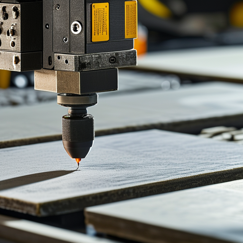
Silicon carbide marking requires more than a high-power laser. The mark must show clear contrast, stable depth, and repeatable speed. A dark surface mark may look impressive, yet fail after cleaning or thermal cycling. Test durability, not appearance alone.
Begin with the required contrast. Light SiC surfaces may need controlled surface oxidation or subtle ablation. Dark materials often require material removal to expose a brighter layer. Mark depth should match the application. For traceability, shallow marks can be sufficient. For harsh environments, deeper grooves may resist wear better. Excessive depth can create stress points or weaken thin components.
Speed depends on pulse energy, repetition rate, scan spacing, and heat control. At 1064 nm, absorption varies with SiC grade, surface finish, contamination, and temperature. Do not assume identical settings will work across every batch. I recommend testing a matrix of pulse widths and scan speeds on actual production samples. Watch the heat-affected zone under magnification. Edges should remain sharp, without cracking or powdery residue.
Measure results. Use optical contrast readings, depth checks, and abrasion tests. Record settings with each material lot. Small changes matter. A faster pass may reduce contrast. A slower pass may increase thermal damage. This trade-off is easy to underestimate. When 1064 nm absorption is insufficient, reconsider beam focus, pulse duration, and surface preparation before increasing power. Sometimes, the best setting is less aggressive.
SiC marking starts with surface compatibility, not machine power. Yole Group’s 2024 Power SiC report estimates the market will grow from about $2.2 billion in 2023 to $4.7 billion by 2029. That growth increases demand for traceable, low-damage identification on wafers, modules, and ceramic parts. Fiber lasers, usually operating near 1,060 nanometers, suit coated or slightly rough SiC surfaces. They offer fast lines and lower operating costs. However, polished SiC may absorb energy unevenly, causing weak contrast or small heat-affected zones.
UV lasers near 355 nanometers are often the safer choice for fine markings. Their shorter wavelength is absorbed more strongly by SiC, supporting shallow ablation and sharper characters. This helps when marking tiny serial codes near sensitive edges. CO₂ lasers, commonly near 10.6 micrometers, can create stronger thermal interaction. They may suit larger graphics or deeper marks, but excessive heat can produce chipping, discoloration, or microcracks. That risk is easy to underestimate.
Tips: Test the actual grade, finish, and coating. Use a microscope after marking. Measure contrast and crack depth, not appearance alone. Start with low pulse energy and multiple passes. My first instinct was choosing fiber for speed, but polished SiC changed that decision. Process data matters more than a catalogue rating. According to Fraunhofer laser-processing guidance, beam overlap, pulse duration, and heat control strongly influence edge quality. A short trial cannot replace production validation.
Choosing a SIC marking laser in 2026 starts with power, but power alone can mislead. For many production trials, 20–50 W provides a practical working range. A 20 W source may suit shallow identification marks and heat-sensitive surfaces. A 50 W source can shorten cycle times and support deeper contrast. However, excessive power may create rough edges, discoloration, or unnecessary heat.
Pulse frequency changes the result. At 20 W and 20 kHz, each pulse carries about 1 mJ before optical losses. At 50 W and 100 kHz, the energy drops to about 0.5 mJ per pulse. Lower frequencies often create stronger individual impacts. Higher frequencies can produce smoother fills and more controlled surface treatment. The correct setting depends on pulse duration, scan speed, spot size, and material grade. Test coupons matter.
In practical trials, I would begin near 30 W and 50 kHz. Then I would adjust one variable at a time. Use small grids, close line spacing, and consistent focus. Inspect edge sharpness under magnification. Measure contrast after cleaning and after repeated handling. I once judged a mark too quickly because it looked excellent immediately after processing. It faded during abrasion testing. That mistake reinforced a simple lesson: visual quality is only one measurement. Record settings, surface temperature, and cycle time before approving a machine. A benchmark guides testing; it does not replace it.
| Laser Power | Pulse Frequency | Approx. Pulse Energy* | Typical Marking Behavior on SiC | Recommended Use | Selection Notes |
|---|---|---|---|---|---|
| 20 W | 20 kHz | 1.00 mJ | Higher energy per pulse; stronger interaction and greater risk of heat accumulation if scanning is slow. | Deep or high-contrast test marks on coated, graphite, or fixture-mounted parts. | Use controlled hatch spacing and multiple lighter passes when surface chipping or excessive thermal damage is a concern. |
| 20 W | 50 kHz | 0.40 mJ | Balanced pulse energy and repetition rate for general-purpose marking. | Text, serial numbers, 2D codes, and moderate-contrast identification marks. | A practical starting point when the required contrast and depth are not yet established. |
| 20 W | 100 kHz | 0.20 mJ | Lower pulse energy with smoother, more distributed energy delivery. | Fine graphics, small characters, and heat-sensitive surface treatments. | May require slower scanning or additional passes to reach the desired contrast or depth. |
| 30 W | 20 kHz | 1.50 mJ | High pulse energy and higher available throughput for more demanding marks. | Deeper identification marks and larger production graphics on robust surfaces. | Verify part fixturing and thermal management before using maximum pulse energy. |
| 30 W | 50 kHz | 0.60 mJ | Good balance of throughput, contrast, and controllable heat input. | Production marking of batch codes, logos, text, and machine-readable symbols. | Often a versatile configuration for mixed SiC part sizes and changing mark layouts. |
| 30 W | 100 kHz | 0.30 mJ | Higher pulse count supports uniform surface treatment and fine detail. | Fine-line marking, dense data codes, and applications requiring reduced per-pulse impact. | Choose suitable scan speed and hatch settings to avoid excessive overlapping pulses. |
| 50 W | 20 kHz | 2.50 mJ | Maximum energy per pulse in this benchmark range; suitable for aggressive material removal. | High-throughput or deeper marking where the part can tolerate concentrated energy. | Use conservative starting parameters because excessive energy can increase debris, cracking, or edge damage. |
| 50 W | 50 kHz | 1.00 mJ | High average power with moderate pulse energy for fast area coverage. | High-volume marking, larger fields, and repeated production cycles. | Confirm the scan head, extraction system, and workholding are rated for the intended duty cycle. |
| 50 W | 100 kHz | 0.50 mJ | High throughput with lower energy per pulse and potentially smoother mark development. | Fast marking of fine text, dense codes, and larger surface areas. | Useful when production speed is important, but validate heat buildup during continuous operation. |
How to Choose a SIC Marking Laser in 2026?
Choosing a laser for silicon carbide marking starts with the smallest feature you must reproduce. A 10–30 µm resolution target demands more than a small advertised spot. Measure the focused spot on the actual work surface, not only in a specification sheet. Lens selection, surface height, coating, and beam quality can change the result. A 20 µm spot may still create a wider heat-affected edge.
Start conservatively. Scan speed controls energy per unit length. If speed is too low, the mark may darken unevenly, create debris, or lose edge definition. If speed is too high, contrast can fade before the required readability is achieved. Compare 10, 20, and 30 µm line features with a calibrated microscope. Record speed, power, pulse frequency, hatch spacing, and pass count. This log becomes valuable when material batches vary.
For dense symbols, a smaller spot can improve corner accuracy, but it may reduce throughput. A larger spot often marks faster and tolerates minor height changes. Fine characters may then close up. Inspect samples after cleaning and thermal cycling. In practical trials, the fastest setting is rarely the most stable. That assumption needs testing. Select the laser configuration that maintains measured resolution, consistent contrast, and an acceptable cycle time.
Choosing a SIC marking laser in 2026 requires more than comparing wattage. Start with heat control. Ask for test marks on your actual stainless steel, coated aluminum, plastic, or heat-sensitive parts. A stable pulse, adjustable frequency, and controlled beam focus can reduce discoloration, warping, and weak contrast. Inspect the mark under normal lighting and after cleaning. Production samples reveal problems that brochures rarely show. Keep samples.
Automation should fit the line, not force a redesign. Check software communication, fixture sensing, barcode input, recipe permissions, and cycle-time records. A practical system can reject an incorrect part before marking begins. That detail matters. Guarding, door interlocks, emergency stops, warning indicators, and documented laser classification should be reviewed by trained personnel. Ask how faults are logged and how maintenance access is controlled. A fast machine is not automatically a safe machine. In my experience, awkward loading creates more risk than slow software.
For ISO 9001 traceability, link each mark to a part number, serial number, operator, recipe, date, and inspection result. Exportable records help during audits and customer complaints. Confirm data retention, user access levels, backup procedures, and calibration evidence. Do not accept “traceable” as a sales phrase. Request a sample report and follow one part through the entire record. Even good systems need disciplined work instructions. We once overlooked a naming mismatch; the laser performed correctly, but the record became difficult to verify. That was a process failure, not a marking failure.